BK21-6C315-BA crankshaft position sensor, BK21-6C315-BA, Ford diesel crankshaft sensor, Ford Ranger crankshaft sensor, Mazda BT-50 BK21-6C315-BA replacement, Ford Transit diesel crankshaft sensor

Ford Diesel Hard Starting? Inspect the BK21-6C315-BA Crankshaft Position Sensor

Diesel engines can sometimes be difficult to start or stall unexpectedly, leading many drivers to suspect fuel or battery problems. However, in many Ford diesel vehicles, the culprit is often the BK21-6C315-BA crankshaft position sensor. Despite its small size, this sensor plays a critical role in engine timing and overall performance.

Why the BK21-6C315-BA Sensor Is Crucial

The crankshaft position sensor provides the engine control unit (ECU) with real-time data on the crankshaft’s rotational speed and exact position.

With accurate signals from this sensor, the ECU can:

  • Control fuel injection timing precisely
  • Maintain smooth engine operation
  • Prevent engine stalling and misfires

If the sensor signal becomes weak or intermittent, the engine may hesitate, stall, or fail to start.

Signs of a Failing Crankshaft Sensor

A failing BK21-6C315-BA sensor rarely fails completely overnight. Most drivers notice gradual symptoms, such as:

  • Longer engine cranking times
  • Random stalling while driving
  • Check engine light activation
  • Reduced power or rough idling

Proper diagnosis is essential, as similar symptoms can also be caused by other engine components.

BK21-6C315-BA crankshaft position sensor, BK21-6C315-BA, Ford diesel crankshaft sensor, Ford Ranger crankshaft sensor, Mazda BT-50 BK21-6C315-BA replacement, Ford Transit diesel crankshaft sensor

Vehicles Using BK21-6C315-BA

The BK21-6C315-BA crankshaft position sensor is widely used across several Ford diesel platforms, including:

  • Ford Ranger 2.2L / 3.2L TDCi
  • Ford Everest diesel models
  • Ford Transit diesel vans
  • Mazda BT-50 diesel versions

These vehicles share similar engine designs, making the sensor interchangeable across multiple models. Highlighting this compatibility is crucial for external buyers looking for replacement parts.

When and How to Replace the Sensor

Once a crankshaft sensor begins to fail, replacement is the most reliable solution. Key points for technicians or experienced buyers:

  1. Disconnect the battery before starting.
  2. Locate the sensor near the engine block or flywheel housing.
  3. Remove the old sensor and install a new BK21-6C315-BA sensor.
  4. Reconnect wiring and clear any stored ECU fault codes.

Using a high-quality replacement sensor ensures accurate signal transmission and long-term engine reliability.

Practical Advice for Ford Diesel Owners

Even though the crankshaft sensor is small, its impact on engine operation is significant. Replacing the BK21-6C315-BA sensor early can prevent:

  • Hard starting
  • Unexpected engine stalls
  • ECU-related warning lights

For Ford Ranger, Everest, Transit, and Mazda BT-50 diesel engines, checking this sensor should always be part of routine troubleshooting for engine performance issues.


Brilliance H530 ABS sensor, 4-wheel ABS sensor, 4097001, 4097002, 4097003, 4097004, Brilliance H530 brake parts

Brilliance H530 4-Wheel ABS Sensors: Precision Braking for Safer Driving

The Brilliance H530 is known for its comfort and reliability, but its braking system depends on precision components. Among them, the 4-wheel ABS sensors (OE: 4097001, 4097002, 4097003, 4097004) are essential. These sensors monitor wheel rotation in real-time and feed accurate data to the ABS control unit, preventing wheel lock and ensuring stability during sudden stops or slippery road conditions.

OE Numbers and Wheel Functions

Wheel OE Number Function
  Front Left    4097001   Provides accurate front-left wheel speed data
  Front Right    4097002   Maintains front-right braking consistency
  Rear Left    4097003   Ensures rear-left wheel stability
  Rear Right    4097004   Supports rear-right braking precision

Brilliance H530 ABS sensor, 4-wheel ABS sensor, 4097001, 4097002, 4097003, 4097004, Brilliance H530 brake parts

Brilliance H530 ABS sensor, 4-wheel ABS sensor, 4097001, 4097002, 4097003, 4097004, Brilliance H530 brake parts

Using original OE sensors guarantees long-lasting performance, consistent braking, and minimizes the risk of ABS failure.

Common Warning Signs

  • ABS warning light on the dashboard
  • Uneven or shuddering braking
  • Brake pedal feels soft or inconsistent

Quick diagnostics with a multimeter or OBD scanner can detect early sensor issues and prevent costly repairs.

Replacement & Maintenance Tips

  • Replace all four sensors at once for balanced performance
  • Always use genuine OE numbers 4097001–4097004
  • Recalibrate the ABS system after installation for maximum accuracy

Regular maintenance ensures your Brilliance H530 continues to deliver precise and reliable braking, protecting both you and your passengers

Brilliance H530 ABS sensor, 4-wheel ABS sensor, 4097001, 4097002, 4097003, 4097004, Brilliance H530 brake parts

Brilliance H530 ABS sensor, 4-wheel ABS sensor, 4097001, 4097002, 4097003, 4097004, Brilliance H530 brake parts

K01165021, Ignition Coil for BAIC Senova X55

BAIC Ignition Coil K01165021 – Technical Overview

The BAIC Ignition Coil K01165021 is an essential component in gasoline engines, responsible for transforming the 12V battery voltage into the high-voltage spark necessary to ignite the air-fuel mixture in the cylinders. Its reliable operation ensures smooth combustion, optimal engine performance, and reduced emissions.

K01165021, Ignition Coil for BAIC Senova X55

Technical Principles

  • Voltage Transformation – Converts low-voltage input into tens of thousands of volts for spark ignition.
  • Copper Windings – High-conductivity primary and secondary coils ensure efficient energy transfer.
  • Heat-Resistant Insulation – Maintains electrical integrity under high engine temperatures.
  • Secure Connectors – Accurate spark timing depends on proper mounting and stable electrical connections.

These technical characteristics are common across most ignition coils, providing a reference framework for understanding coil function in other applications.

Common Fault Symptoms

A malfunctioning K01165021 ignition coil may present the following issues:

  • Engine misfires or rough idling
  • Reduced power during acceleration
  • Increased fuel consumption
  • Illumination of the check engine light

Timely diagnosis is critical to prevent damage to spark plugs and other ignition components.

Diagnostic and Maintenance Guidelines

  1. Visual Inspection – Check for cracks, burns, or contamination on the coil body.
  2. Electrical Testing – Measure primary and secondary resistance using a multimeter; compare with OEM specifications.
  3. On-Vehicle Testing – Use a diagnostic scanner to identify misfire codes or other coil-related faults.
  4. Maintenance Practices – Inspect coils regularly, replace spark plugs concurrently, keep connectors and wiring clean, and ensure heat-resistant insulation is intact.

Proper understanding and maintenance of the BAIC K01165021 coil ensures long-term reliability and consistent engine performance.

6C11-12K073-AC, 6C1112K073AC, U20218230B, Camshaft Position Sensor for Ford

Ford 6C11-12K073-AC Camshaft Position Sensor – Technical Overview & Diagnostics

The 6C11-12K073-AC Camshaft Position Sensor (CMP) is an OE component manufactured by Jiangling Motors Corporation for Ford vehicles under the Ford–JMC joint production program. It monitors camshaft position and provides precise signals to the ECU for fuel injection timing and ignition synchronization.

6C11-12K073-AC, 6C1112K073AC, U20218230B, Camshaft Position Sensor for Ford

Function in Engine Management

The CMP sensor is critical for:

  • Cylinder phase identification during engine start
  • Camshaft and crankshaft synchronization
  • Sequential fuel injection timing
  • Emission control and misfire monitoring

A faulty or distorted CMP signal can trigger fault code P0340, cause rough idle, extended cranking, or reduced engine performance.

Signal Characteristics

  • 3-wire Hall-effect sensor
  • 5V reference supply, 0–5V digital output
  • Factory-calibrated phase alignment

Even minor waveform distortion or phase deviation can cause intermittent synchronization errors. OE calibration ensures signal reliability and ECU compatibility.

Diagnostic Tips

Before replacing the sensor, verify:

  • Stable 5V supply and proper ground
  • Correct mechanical timing
  • Crankshaft sensor signal integrity
  • CMP waveform consistency

Replacing the sensor without checking these factors may not resolve synchronization faults.

Common Observations in the Field

  • Heat can affect Hall element output → intermittent misfires
  • Connector corrosion may reduce signal amplitude
  • Mechanical timing drift can cause ECU misinterpretation

Understanding these factors helps technicians avoid misdiagnosis and unnecessary replacements.

  • 6C11-12K073-AC, 6C1112K073AC, U20218230B, Camshaft Position Sensor for Ford

OE Reference

  • OE Number: 6C11-12K073-AC
  • Alternative: 6C1112K073AC
  • Cross Reference: U20218230B

Always confirm engine variant or VIN before installation.

Isuzu 8-98098257-5, Isuzu EGR Valve, 4HK1 Engine EGR Valve, Electronic EGR Valve Isuzu, Isuzu OE EGR Valve, Isuzu 8-98098257-5 EGR valve, Genuine OE EGR valve for 4HK1 engine

Isuzu 8-98098257-5 EGR Valve for 4HK1 Engine – Genuine OE Original Equipment Part

Buy genuine Isuzu 8-98098257-5 EGR valve, an original OE part for 4HK1 diesel engines (NQR, FTR, FRR). Learn symptoms, replacement guide & OE compatibility for stable engine performance and emission compliance.

The Isuzu 8-98098257-5 EGR (Exhaust Gas Recirculation) valve is a genuine OE part for 4HK1 diesel engines, commonly installed in Isuzu NQR, FTR, and FRR trucks. Designed for heavy-duty operation, it precisely regulates exhaust gases to lower combustion temperatures and reduce NOx emissions, ensuring stable engine performance.

Isuzu 8-98098257-5, Isuzu EGR Valve, 4HK1 Engine EGR Valve, Electronic EGR Valve Isuzu, Isuzu OE EGR Valve, Isuzu 8-98098257-5 EGR valve, Genuine OE EGR valve for 4HK1 engine

Function & Benefits

Recirculates exhaust gases to optimize combustion

Maintains emission compliance

Improves fuel efficiency and overall engine reliability

Common Symptoms of EGR Valve Failure

Check engine light illuminated

Rough idle or power loss under load

Black smoke from exhaust

Fault codes P0401 / P0403

Failures are often caused by carbon buildup or electronic actuator issues. Timely replacement restores proper EGR valve function and ensures emission stability.

Application & OE Details

OE Number: 8-98098-257-5

Engine: 4HK1

Models: Isuzu NQR / FTR / FRR

Type: Electronic EGR Valve

Isuzu 8-98098257-5, Isuzu EGR Valve, 4HK1 Engine EGR Valve, Electronic EGR Valve Isuzu, Isuzu OE EGR Valve, Isuzu 8-98098257-5 EGR valve, Genuine OE EGR valve for 4HK1 engine

Isuzu 8-98098257-5, Isuzu EGR Valve, 4HK1 Engine EGR Valve, Electronic EGR Valve Isuzu, Isuzu OE EGR Valve, Isuzu 8-98098257-5 EGR valve, Genuine OE EGR valve for 4HK1 engine

Note: Always confirm the OE number for correct fitment and ECU compatibility before replacement.


car Wheel Speed Sensors, car Yaw Rate Sensor, car Steering Angle Sensor, Car ESP Control Unit (ECU), Car Hydraulic Modulator Car ESP System, Auto Electronic Stability Program

Main Components of the ESP (Electronic Stability Program)

1、Wheel Speed Sensors
There are four wheel speed sensors, one on each wheel. They measure how fast each wheel is turning and help the system detect if a wheel is slipping or locking up.
2、Yaw Rate Sensor
This sensor measures how much the car is rotating around its vertical axis — in simple terms, it tells whether the car is skidding or swinging sideways. It’s a very sensitive sensor that can detect even tiny movements of the car’s body while driving.
3、Steering Angle Sensor
This sensor tracks how much the driver turns the steering wheel. It helps the system understand the driver’s steering intention and compare it with how the car is actually moving.
4、ESP Control Unit (ECU)
The control unit is the “brain” of the ESP system. It collects data from all the sensors, analyzes the car’s driving condition, and decides when to step in. If it detects a possible loss of control, it sends signals to adjust the brakes or engine power to keep the car stable.
5、Hydraulic Modulator
This part controls the brake pressure in the braking system. It can apply different braking forces to each wheel individually, helping the car stay balanced and stable when turning or driving on slippery roads.

car Wheel Speed Sensors, car Yaw Rate Sensor, car Steering Angle Sensor, Car ESP Control Unit (ECU), Car Hydraulic Modulator Car ESP System, Auto Electronic Stability Program

Working Principle of the ESP (Electronic Stability Program) System

When the vehicle encounters a fallen obstacle ahead and the driver makes an emergency left steering maneuver to avoid it, the steering angle sensor detects the driver’s steering intention and transmits this information to the ESP electronic control unit (ECU).
However, due to the vehicle’s speed and inertia, the vehicle body still tends to move straight toward the obstacle. Since the front wheels are already executing a left-turn operation, the rear of the vehicle will inevitably swing out to the right.
At this moment, the yaw rate sensor detects the vehicle’s tail-swing signal and sends it to the control unit, which immediately applies braking force to the left rear wheel. This generates a counteracting force that suppresses the rear-end swing and helps the vehicle maintain its intended direction of travel.
Next comes the counter-steering phase. After completing the initial left-turn maneuver, the driver typically straightens the steering wheel or even turns slightly to the right. Due to this oversteering, the rear of the vehicle now tends to swing out to the left. To counteract this yaw moment, the ESP system applies braking force to the left front wheel, creating an opposing torque that stabilizes the vehicle and reduces the tail-swing effect.
Through these coordinated and timely interventions, the ESP system assists the vehicle in returning to the driver’s intended driving trajectory, maintaining stability, and safely avoiding danger.
This describes the working principle and interaction mechanism of the components that make up the ESP vehicle stability control system.

Reminder:
The ESP system is an electronic driver-assistance system. While it can significantly improve vehicle stability and help prevent skidding or loss of control in emergency situations, it does not guarantee 100% effectiveness. Under extreme driving conditions, there is still a risk of losing control.
In addition, not all vehicles use the name “ESP” (Electronic Stability Program) for this system. Different manufacturers may use different names, such as VSC (Vehicle Stability Control), ESC (Electronic Stability Control), or DSC (Dynamic Stability Control).

car engine electronic control unit ECU, car Intake temperature sensor, car Water temperature sensor, auto Crankshaft position sensor supplier, auto Camshaft position sensor supplier, car Knock sensor supplier, car Oxygen sensor sales, auto electronic control unit ECU supplier, car Throttle position pedal sensor, car Throttle position sensor sales, car spark plug supplier

What is the role of the engine’s electronic control unit (ECU)?

The event-driven and responsiveness of the car engine and other intelligent components of the car are all collected by different data sensing elements, and then transmitted back to the engine’s electronic control unit, also known as the ECU, through the transmission line. After the electronic control unit summarizes and analyzes the data, it generates new instructions, and finally sends the instructions to the actuators that respond to the instructions through the transmission line for execution. This is the basic principle that the engine fuel system can inject on time, the spark plug can ignite on time, and the accelerator pedal can be ready to control the amount of oil. This series of precise control is inseparable from the engine’s electronic control unit ECU.

car engine electronic control unit ECU, car Intake temperature sensor, car Water temperature sensor, auto Crankshaft position sensor supplier, auto Camshaft position sensor supplier, car Knock sensor supplier, car Oxygen sensor sales, auto electronic control unit ECU supplier, car Throttle position pedal sensor, car Throttle position sensor sales, car spark plug supplier

Which sensors does the engine electronic control unit ECU use to issue different commands?

1. Throttle position sensor, there is a throttle position sensor on the throttle. It is responsible for converting the throttle opening and the speed of the opening change into a voltage signal and transmitting it to the electronic control unit to calculate the amount of fuel injection.

2. Intake temperature sensor, at the other end of the throttle body, there is an intake temperature sensor, which is used to measure the intake temperature. Air at different temperatures has different masses when the volume is the same, and the oxygen content is also different. Therefore, the electronic control unit can correct the injection amount according to the intake temperature to obtain the best air-fuel ratio.

3. Camshaft position sensor, its function is to collect the rotation angle of each cam on the camshaft to identify whether the cylinder is in the compression stroke to determine the ignition time of the spark plug and the injection time of the injector.

4. Knock sensor, it is responsible for detecting the combustion and explosion intensity of the engine, so as to effectively send the knock of an engine. The combustible mixture accumulated in the cylinder explodes and burns in an instant, causing the pressure and temperature of the gas in the cylinder to suddenly increase several times, resulting in a sharp knocking sound, which will cause the engine to overheat and reduce power, and in severe cases, it will also cause deformation of the machine parts. This is deflagration.

5. Crankshaft position sensor, which is responsible for detecting the rotation angle of the crankshaft and the speed of the engine. The rotation angle can determine whether the piston is at the top dead center position. Combined with the data of the camshaft position sensor, it can accurately identify when to ignite which cylinder.

6. Water temperature sensor, which has similar functions to the intake air temperature sensor, is generally installed in the pipeline of the cooling system and is responsible for monitoring the temperature of the coolant. By identifying the temperature, it can judge the operating conditions of the engine to decide whether to adjust the oil and gas supply.

7. Oxygen sensor, which is installed in the exhaust pipe to detect the oxygen concentration in the exhaust gas. The higher the oxygen concentration, the less complete the cylinder combustion. The electronic control unit can adjust the injection amount, thereby controlling the air-fuel ratio of the mixer in the intake manifold within a reasonable range.

8. Throttle position pedal sensor, its function is to control the opening of the throttle. When the driver steps on the accelerator pedal, it actually transmits a throttle pedal position signal to the electronic control unit. The electronic control unit calculates the opening of the throttle based on this signal. The larger the opening, the more air enters.

car engine electronic control unit ECU, car Intake temperature sensor, car Water temperature sensor, auto Crankshaft position sensor supplier, auto Camshaft position sensor supplier, car Knock sensor supplier, car Oxygen sensor sales, auto electronic control unit ECU supplier, car Throttle position pedal sensor, car Throttle position sensor sales, car spark plug supplier

Summary:

The data from all the above sensors are the basis for the engine’s air supply, fuel supply, injection control and ignition. The sensors convert these data into voltage signals and transmit them to the electronic control unit through wires. The electronic control unit calculates and processes them to obtain accurate and correct action instructions, which are then transmitted to various actuators via wires, ultimately achieving fuel injection, ignition and precise oil control.

electric power steering system (EPS), car steering shaft, auto steering booster, auto steering screw, car rubber dust cover, auto steering tie rod, auto universal joint, car steering booster device, auto electric motor, car torque sensor, mechanical hydraulic power steering system (HPS), electronic hydraulic power steering system (EHPS)

How does the power steering system work?

What is power steering?

  There are two main types of automotive steering systems: mechanical steering and power steering. Because the design of the mechanical steering system is relatively simple, and the driver’s physical strength is used as the steering energy, the steering wheel is heavy and difficult to turn, so the power steering system has emerged. The power steering system uses external power to help the driver achieve easy steering, just like the power of the foot on the brake. There are three main types of common power steering systems: mechanical hydraulic power steering system (HPS), electronic hydraulic power steering system (EHPS), and electric power steering system (EPS). Among them, the electronic hydraulic power steering system (EPS) is widely used in commercial vehicles, and the electric power steering system is widely used in passenger cars. As environmental protection becomes stricter, the mechanical hydraulic power steering system and the electronic hydraulic power steering system not only have high power consumption but also have hydraulic oil leakage problems, which do not meet environmental protection requirements. The market share of the two is gradually replaced by EPS.

Components of the Electric Power Steering System

  The electric power steering system consists of a steering wheel, a steering shaft, a steering booster, a steering screw, a rubber dust cover and a steering tie rod. Since the steering wheel needs to adjust the angle, a universal joint is also installed on the steering shaft to achieve power transmission at different angles.

electric power steering system (EPS), car steering shaft, auto steering booster, auto steering screw, car rubber dust cover, auto steering tie rod, auto universal joint, car steering booster device, auto electric motor, car torque sensor, mechanical hydraulic power steering system (HPS), electronic hydraulic power steering system (EHPS)

How does the electric power steering system work?

  There is a steering booster device, which is composed of an electric motor, a torque sensor and an electronic control unit. The power supply in this structure comes from the on-board battery. When the steering wheel is working, the power is transmitted to the steering shaft through the steering wheel. After the torque sensor recognizes the steering angle and steering force, it feeds the data back to the electronic control unit. After analysis and processing, the electronic control unit forms the final power-assist command and sends it to the motor. The motor converts it into different sizes of power-assist voltage according to the command requirements to drive the gear shaft of the motor to rotate. Since the gear shaft and the power-assist gear are meshed, the power will be transmitted to the power-assist gear. The force of the power-assist gear and the driver’s manual steering are superimposed to form the final combined torque, which is finally transmitted to the steering screw through the steering shaft to achieve power steering.

electric power steering system (EPS), car steering shaft, auto steering booster, auto steering screw, car rubber dust cover, auto steering tie rod, auto universal joint, car steering booster device, auto electric motor, car torque sensor, mechanical hydraulic power steering system (HPS), electronic hydraulic power steering system (EHPS)

Summary:

  Different models on the market have different ways of implementing electric power steering. Some power steering mechanisms are installed at the upper end of the steering shaft, while others are installed at the end of the steering shaft. However, the ultimate goal is to help the driver. The power steering is adjustable with speed, and the controllability is good.

car steering system, car mechanical steering, car power steering, car steering column, car steering wheel, car steering rod

What are the design principles of automobile mechanical steering systems?

The system responsible for turning and changing direction of the car is called the car steering system. The commonly used steering systems on the market are mainly divided into two categories: mechanical steering and power steering.

The mechanical steering system is connected by the steering wheel and the steering column. The steering column head is connected to the tie rod between the two wheels. When the steering wheel turns, it will drive the steering column to turn. The steering column will pull the tie rod to the left or right, and the wheels can turn left or right. This is the most basic principle of steering wheel steering. Because this design is too rough, when the steering wheel is not dead, the wheels have already turned to the maximum angle, that is, the steering angle of the steering wheel and the wheel is the same. The industry says that the steering transmission is 1:1, that is, the steering wheel turns the same angle as the steering wheel. This design does not meet the steering parameter regulations of motor vehicles. This design is very dangerous for motor vehicles, because the transmission ratio is 1:1. When the steering wheel turns one degree, the wheel will turn one degree. If the steering wheel turns 5 degrees, the wheel will also turn 5 degrees. If the driver makes a wrong turn on a rugged road due to the shaking of the vehicle, the wheel will respond immediately, which may cause a major traffic accident, which will be very dangerous.

car steering system, car mechanical steering, car power steering, car steering column, car steering wheel, car steering rodIn order to solve this problem, a rack-and-pinion steering design was developed. A bevel gear, also called a helical gear or steering gear, was added to the end of the steering column. This gear meshes with a rack, which is connected to the front wheel through a steering rod. When the steering wheel is turned, the steering gear drives the rack to move left and right, which drives the rod to push and pull the front wheel to achieve a turn. Due to the addition of racks and pinions in this design, the steering transmission ratio becomes smaller. According to the requirements of the national standard, this ratio is between 12:1 and 24:1. Therefore, for a family car, when the wheel is returned to the correct position, the steering wheel needs to be turned one and a half turns before it can be stopped. In other words, the steering wheel needs to be turned three times from the extreme left to the extreme right. Now you should know why the steering wheel is designed to be round.

car steering system, car mechanical steering, car power steering, car steering column, car steering wheel, car steering rod

The current optimized design is still relatively rough, because its steering power transmission is relatively direct, and the steering feedback felt by the hand is also very direct. In layman’s terms, when encountering potholes, the vibration of the wheel will be directly transmitted to the hand through this series of connection components, which is often called the hand-beating phenomenon, and sometimes even the steering wheel cannot be held. Therefore, in order to optimize the design, it was modified again, and the original gear rack type direct meshing connection was changed to a method of using multiple steel balls to transfer power, and the steel balls were used to circulate along the grooves to transmit steering power. In this design, the circular movement of the steel balls in the grooves can effectively absorb the impact from the road surface and play a good shock-absorbing role, so that the driver can get a smoother steering feel. However, this design cost is relatively high, and is usually only used in buses, trucks and off-road vehicles.

car steering system, car mechanical steering, car power steering, car steering column, car steering wheel, car steering rod

Summary:

  The steering system optimized by the above two rounds cannot actually meet the safety and comfort requirements of modern cars. The design of the mechanical steering system is relatively simple. It uses the driver’s physical strength as the steering energy, which will require the driver to consume a lot of physical strength. Because the steering force used is different due to different vehicle loads, when using this type of steering system, the steering wheel will be heavy and very difficult to turn.

auto clock spring supplier, car clock spring replacement, auto clock spring assy, car spiral cable, auto clock spring repair, car clock spring failure, car Clock spring steering wheel, symptoms of faulty clock spring, Clock spring function

How to replace a broken car clock spring?

Repairing your car’s clock spring (or spiral cable) can be a little tricky and requires caution, as it is a critical part of your car’s airbag system. It connects the steering wheel to the car’s electrical system, allowing features like the horn, airbags, and cruise control to work while still allowing the steering wheel to turn. It’s not an easy task, so replacing a faulty clock spring is usually a better option than repairing it.

What are the steps to replace a clock spring?

1. Disconnect the battery

Disconnect the battery, safety first. Disconnect the negative terminal of the vehicle’s battery before starting. This prevents any electrical problems, accidental airbag deployment, or short circuits when working around the airbag system and steering column. A simple wrench is enough to loosen the bolt on the negative terminal of the battery. Once loosened, completely unplug the cable from the battery column.

auto clock spring supplier, car clock spring replacement, auto clock spring assy, car spiral cable, auto clock spring repair, car clock spring failure, car Clock spring steering wheel, symptoms of faulty clock spring, Clock spring function

2. Remove the airbag

Be careful when working on the airbag and make sure the vehicle is completely powered off. Use a screwdriver or special tool to unscrew the airbag module from the steering wheel and carefully disconnect the airbag wiring from the clock spring. Once the airbag is out, you may need to disconnect the electrical connector connected to it. On most cars, the airbag is secured by screws or bolts on the back of the steering wheel. Some vehicles also come with a plastic panel that needs to be removed to expose the airbag mounting screws. After removing the airbag, you will find an electrical connector that connects to the vehicle’s electrical system. Gently disconnect it to fully release the airbag. Always be careful when handling airbags, as they are explosive devices. Avoid touching the airbag deployment area.

3. Remove the steering wheel

After removing the airbag module, you will see a large center nut that holds the steering wheel in place. At this time, you can use the steering wheel rail to remove the center nut that holds the steering wheel. Be sure to pay attention to the accurate alignment of the steering wheel on the shaft, as you will need to realign it during installation. If the steering wheel does not come off easily after loosening the center nut, you may need a steering wheel puller. This tool can help remove the steering wheel without damaging the column or clock spring underneath. Before removing the steering wheel, mark its position on the steering column with a marker so that it is accurately aligned when reassembled.

auto clock spring supplier, car clock spring replacement, auto clock spring assy, car spiral cable, auto clock spring repair, car clock spring failure, car Clock spring steering wheel, symptoms of faulty clock spring, Clock spring function

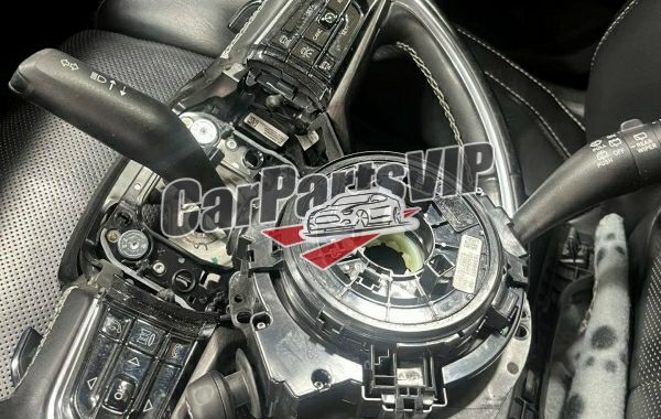
4. Locate and check the clock spring

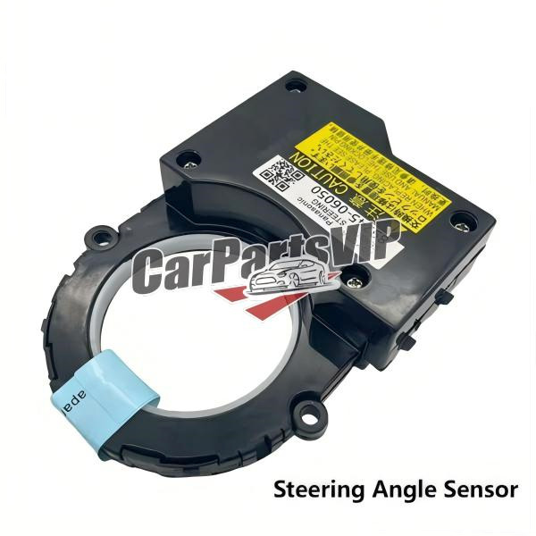
The clock spring is a coiled wire device located just below the steering wheel. It is essential for maintaining electrical connections for devices such as the horn, airbags, cruise control, and steering wheel buttons, while allowing the steering wheel to rotate freely. The clock spring may be secured with screws or clips. Remove these fasteners with a screwdriver, then carefully pull out the clock spring. Be sure not to yank on the wires, or they will be damaged. Look for any visible damage, such as broken wires, fraying, or obvious cracks in the plastic casing. If you find any problems, replace them in time.

auto clock spring supplier, car clock spring replacement, auto clock spring assy, car spiral cable, auto clock spring repair, car clock spring failure, car Clock spring steering wheel, symptoms of faulty clock spring, Clock spring function

5. Replace the clock spring (if damaged)

If the clock spring is broken, you need to replace it with a new one. Be sure to get the correct part number and make sure the replacement clock spring matches the model and year of your vehicle. If you are unsure, you can get the part number from the damaged car and consult an auto parts supplier. Before installing a new clock spring, make sure the internal coil is properly aligned (do not over-wind or loosen it). If the coil is not aligned, it may break when the steering wheel is rotated. Some clock springs have indicators (such as arrows) to show the correct alignment. Slide the new clock spring into place and secure it with screws or clips to ensure it is properly seated. Make sure the spring is centered so it has a full range of motion and does not break when you reinstall the steering wheel.

6. Reinstall the steering wheel

Put the steering wheel back together, making sure the clock spring is aligned correctly. Align the steering wheel with the mark you made earlier and bolt it back to the steering column, tightening the center nut. Reinsert the airbag’s electrical connector and secure the airbag module back to the steering wheel. Make sure the mounting bolts or screws are tight. Once everything is back in place, reconnect the battery and tighten it. Carefully reassemble everything, starting with the steering wheel, airbag module, and electrical connector.

7. Test the system

After reassembly, check to make sure everything is working properly. Turn on the vehicle and check the airbag light on the dashboard, test the horn, cruise control buttons, and any other steering wheel controls to make sure everything is working properly.

Tips:

  During the operation, work carefully and slowly, and never break or misplace parts because of haste. Always be careful when operating the airbag. Improperly aligning the steering wheel during operation can cause the clock spring to break when you turn the steering wheel, so make sure it is positioned exactly as it was before removal.
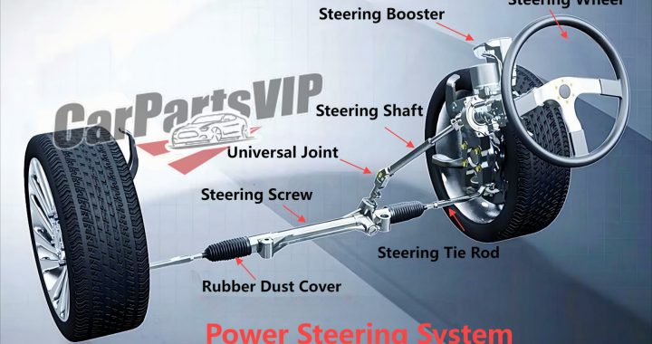
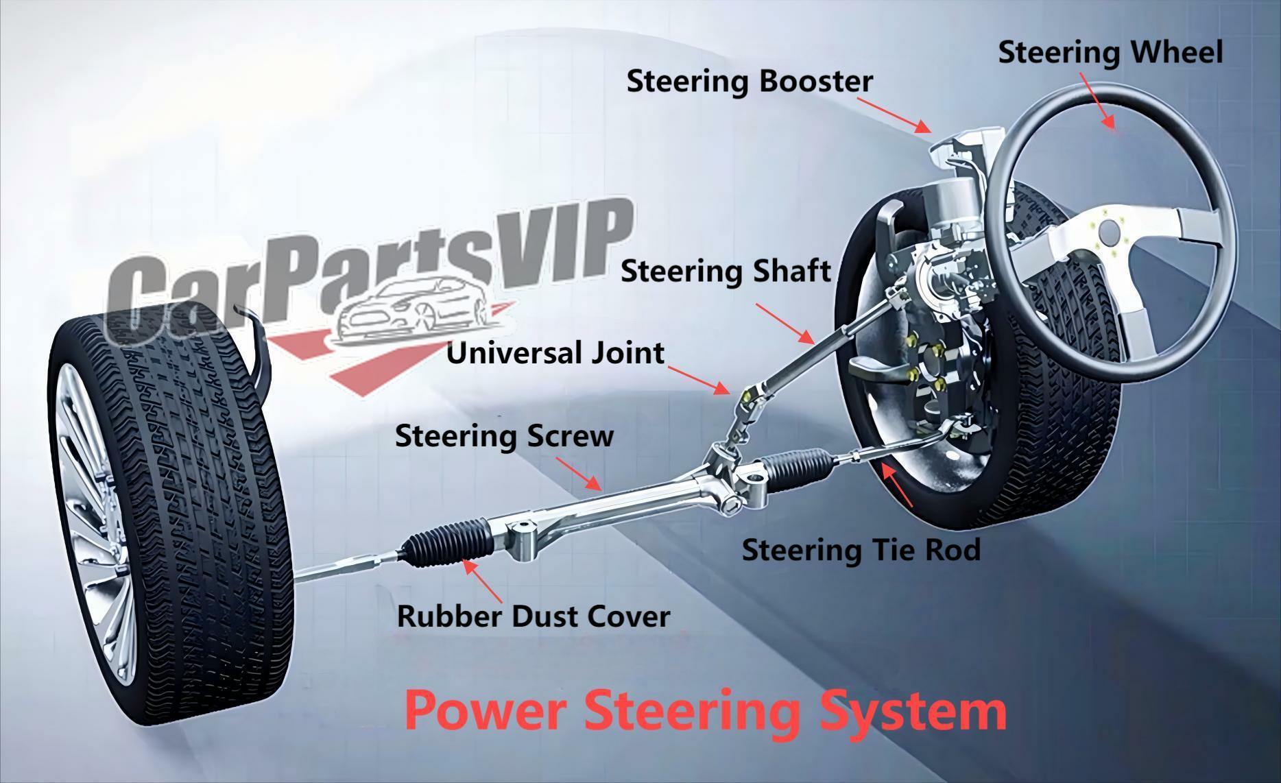
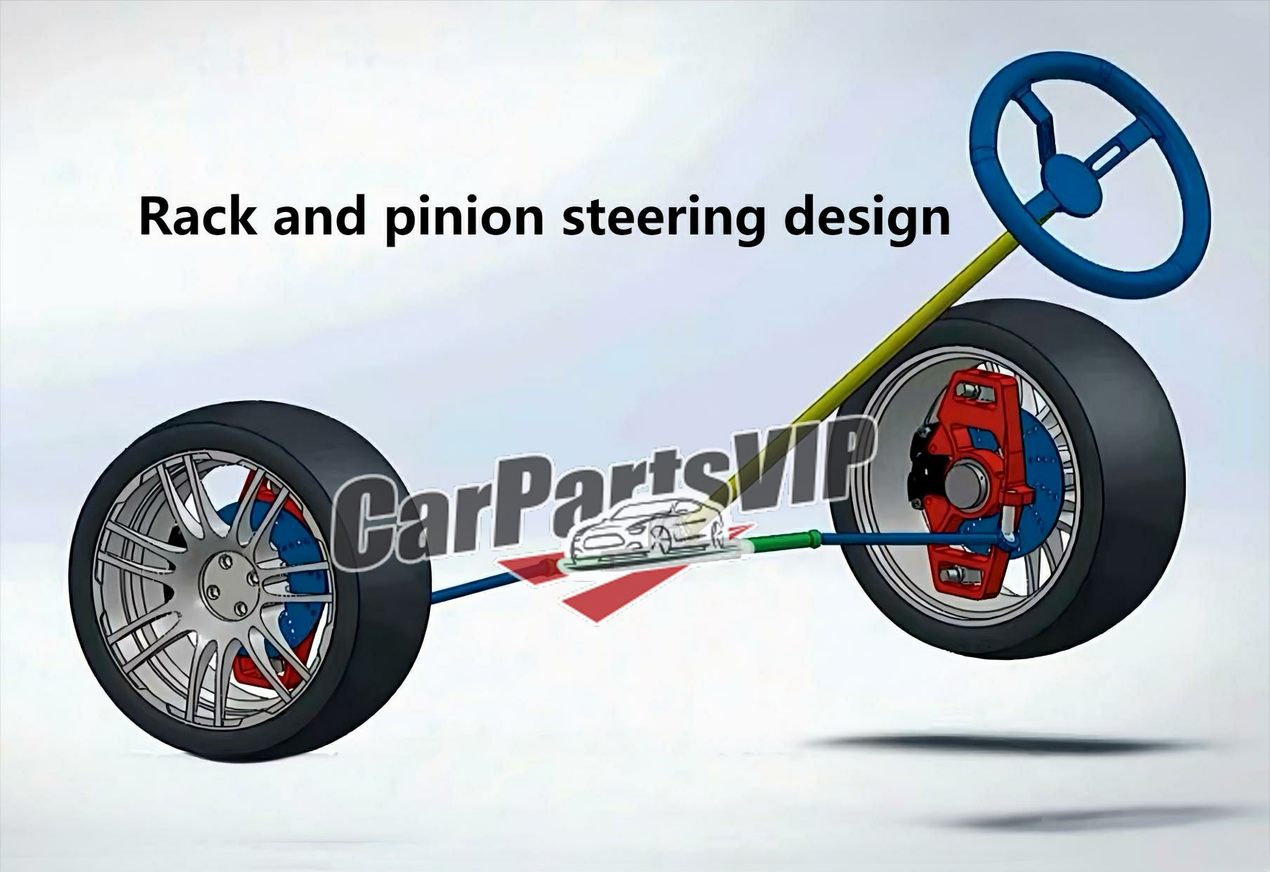
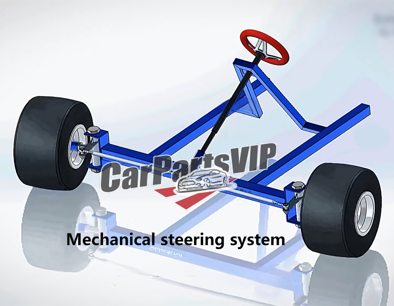